


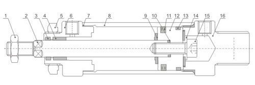
Series: MAL Series Mini Cylinder
|
Motion Pattern |
Double Action or Single Action |
|||||
|
Working Medium |
Air |
|||||
|
Operating Pressure Range |
0.1~0.9MPa |
|||||
|
Ensured Pressure Resistance |
1.35MPa |
|||||
|
Operating Temperature Range |
-5~70℃ |
|||||
|
Operating Speed Range |
30~800mm/s |
|||||
|
Bore(mm) |
16 |
20 |
25 |
32 |
40 |
|
|
Motion pattern |
Double Action or Single Action |
|||||
|
Working Medium |
Air |
|||||
|
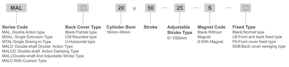
Fixed Type |
Normal Type LB Type FA Type SDB Type |
|||||
|
Operating Voltage Range |
0.1~0.9MPa |
|||||
|
Ensured Pressure Resistance |
1.35MPa |
|||||
|
Operating Temperature Range |
-5~70℃ |
|||||
|
Operating Speed Range |
30~800mm/s |
|||||
|
Buffer Type |
Standard Type |
Anti-crash cushion |
||||
|
Damping Type |
- |
Adjustable cushion |
||||
|
Port Size |
M5×0.8 |
G1/8" |
G1/8" | G1/8" |
G1/4" |
|
|
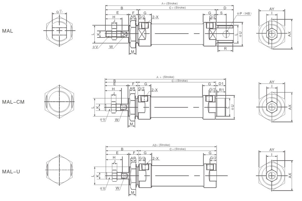
Bore/Symbol |
A |
A1 |
A2 |
B |
C |
D |
D1 |
E |
F |
G |
H |
I |
J |
K |
|
16 |
110 |
114 |
98 |
38 |
56 |
16 |
16 |
22 |
16 |
10 |
16 |
10 |
5 |
M6×1 |
|
20 |
131 |
122 |
110 |
40 |
70 |
21 |
12 |
28 |
12 |
16 |
20 |
12 |
6 |
M8×1.25 |
|
25 |
135 |
128 |
114 |
44 |
70 |
21 |
14 |
30 |
14 |
16 |
22 |
17 |
6 |
M10×1.25 |
|
32 |
141 |
128 |
114 |
44 |
70 |
27 |
14 |
30 |
14 |
16 |
22 |
17 |
6 |
M10×1.25 |
|
40 |
165 |
152 |
138 |
46 |
92 |
27 |
14 |
32 |
14 |
22 |
24 |
17 |
7 |
M12×1.25 |
|
Bore/Symbol |
L |
M |
P |
Q |
R |
R1 |
S |
U |
V |
W |
X |
AR |
AX |
AY |
|||||||||||||
|
16 |
M16×1.5 |
14 |
6 |
12 |
14 |
14 |
9 |
24 |
6 |
5 |
M5 |
6 |
25 |
22 |
|||||||||||||
|
20 |
M22×1.5 |
10 |
8 |
16 |
19 |
10 |
12 |
29 |
8 |
6 |
G1/8" |
7 |
33 |
29 |
|||||||||||||
|
25 |
M22×1.5 |
12 |
8 |
16 |
19 |
12 |
12 |
34 |
10 |
8 |
G1/8" |
7 |
33 |
29 |
|||||||||||||
|
32 |
M24×2.0 |
12 |
10 |
16 |
25 |
12 |
15 |
39.5 |
12 |
10 |
G1/8" |
8 |
37 |
32 |
|||||||||||||
|
40 |
M30×2.0 |
12 |
12 |
20 |
25 |
12 |
15 |
49.5 |
16 |
14 |
G1/4" |
9 |
37 |
41 |
|||||||||||||
|
Symbol |
A |
A1 |
A2 |
B |
C |
D |
D1 |
E |
F |
G |
H |
I |
J |
||||
|
Bore/Stroke |
0-50 |
51-100 |
0-50 |
51-100 |
0-50 |
51-100 |
0-50 |
51-100 |
|||||||||
|
20 |
131 |
156 |
122 |
147 |
110 |
135 |
40 |
70 |
95 |
21 |
12 |
28 |
12 |
16 |
20 |
12 |
6 |
|
25 |
135 |
160 |
160 |
153 |
114 |
139 |
44 |
70 |
95 |
21 |
14 |
30 |
14 |
16 |
22 |
17 |
6 |
|
32 |
141 |
166 |
166 |
153 |
114 |
139 |
44 |
70 |
95 |
27 |
14 |
30 |
14 |
16 |
22 |
17 |
6 |
|
40 |
165 |
190 |
190 |
177 |
138 |
163 |
46 |
92 |
117 |
27 |
14 |
32 |
14 |
22 |
24 |
17 |
7 |
|
Bore/Symbol |
K |
L |
M |
P |
Q |
R |
R1 |
S |
U |
V |
W |
X |
AR |
AX |
AY |
||
|
20 |
M8×1.25 |
M22×1.5 |
10 |
8 |
16 |
19 |
10 |
12 |
29 |
8 |
6 |
G1/8" |
7 |
33 |
29 |
||
|
25 |
M10×1.25 |
M22×1.5 |
12 |
8 |
16 |
19 |
12 |
12 |
34 |
10 |
8 |
G1/8" |
7 |
33 |
29 |
||
|
32 |
M10×1.25 |
M24×2.0 |
12 |
10 |
16 |
25 |
12 |
15 |
39.5 |
12 |
10 |
G1/8" |
8 |
37 |
32 |
||
|
40 |
M12×1.25 |
M30×2.0 |
12 |
12 |
20 |
25 |
12 |
15 |
49.5 |
16 |
14 |
G1/4" |
9 |
47 |
41 |
||
|
Bore/Symbol |
A |
A1 |
B |
C |
E |
F |
G |
H |
I |
J |
K |
|
20 |
150 |
147 |
40 |
70 |
28 |
12 |
16 |
20 |
12 |
6 |
M8×1.25 |
|
25 |
158 |
155 |
44 |
70 |
30 |
14 |
16 |
22 |
17 |
6 |
M10×1.25 |
|
32 |
158 |
155 |
44 |
70 |
30 |
14 |
16 |
22 |
17 |
6 |
M10×1.25 |
|
40 |
184 |
180 |
46 |
92 |
32 |
14 |
22 |
24 |
17 |
7 |
M12×1.25 |
|
Bore/Symbol |
L |
M |
U |
V |
W |
X |
AR |
AX |
AY |
T |
|||||||||
|
20 |
M22×1.5 |
10 |
29 |
8 |
6 |
G1/8" |
7 |
33 |
29 |
19 |
|||||||||
|
25 |
M22×1.5 |
12 |
34 |
10 |
8 |
G1/8" |
7 |
33 |
29 |
21 |
|||||||||
|
32 |
M24×1.5 |
12 |
39.5 |
12 |
10 |
G1/8" |
8 |
37 |
32 |
21 |
|||||||||
|
40 |
M30×2.0 |
12 |
49.5 |
16 |
14 |
G1/4" |
9 |
47 |
41 |
21 |
|||||||||
|
|
|
|
Bore(mm) |
Standard Stroke |
Max.Stroke(mm) |
Permissible Stroke(mm) |
|
16 |
25,50,75, 80,100 ,125,160,175,200 |
300 |
500 |
|
20 |
25,50,75,80,100,125,160,175,200, 250,300 |
500 |
650 |
|
25 |
25,50,75,80,100,125,160,175,200,250,300,350,400,450,500 |
500 |
650 |
|
32 |
25,50,75,80,100,125,160,175,200,250,300,350,400,450,500 |
500 |
650 |
|
40 |
25,50,75,80,100,125,160,175,200,250,300,350,400,450,500 |
500 |
650 |
Accurate requlation of an optimal air fl...
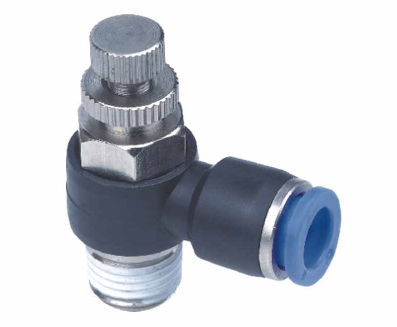
Accurate regulation of an optimal airflo...
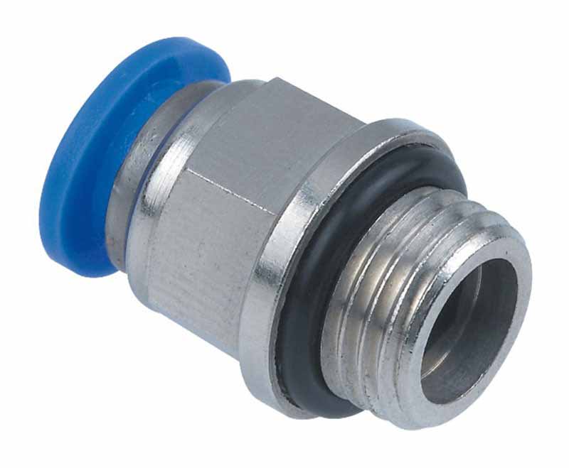
One-Touch push-to-connect configuration ...


© 2026 XCPC Pneumatic. All rights reserved.